Week 1
Starting off the REU I had to be IRB qualified. The IRB training was long and extremely tedious. While they were interesting at points, for the most part they were boring and repetitive. However I did learn a lot about the importance of preventing conflicts of interests in research and the proper ways to keep research information private. The most interesting parts was reading about how the standards came into place after someone did something clearly wrong (Tuskegee study, Human experiments done by Nazis, and the Stanford prison experiment).
Week 2
This week started on the two projects that I will be working on this summer. The first one about the about trust of unmanned aerial vehicles (UAVs) required me to catch up by reading a few papers about where the project is at the current moment. The test involved having two groups of people; people who where trained about the artificial intelligence and those who were not. Surprisingly the results had shown that people who were trained had less trust of the machine. The next task that I had to accomplish was to find out the best way of communicating with the elderly. This was not as easy of a task as most result dealt with the benefits of communication and not the how to. I was able to find however some good information such as do not command them, communicate clearly, express patience and treat them like you would others just to name a few.
Week 3
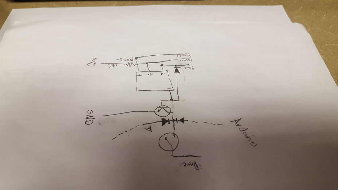
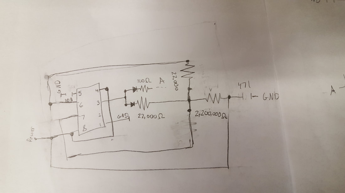
This week I began searching for dealing with the elderly pertaining to usage of social media. This then moved to the topics of circuitry as to help rebuild a circuit with my Mentor Doctor Anderson. The first thing I had to do was draw some schematics of the circuit. This was very challenging as I had to learn how to read schematics first then learn the symbols before starting to draw them. It was very challenging to draw and I did mess up the connections a few times but I did manage to finished two schematics for the circuit.
Week 4
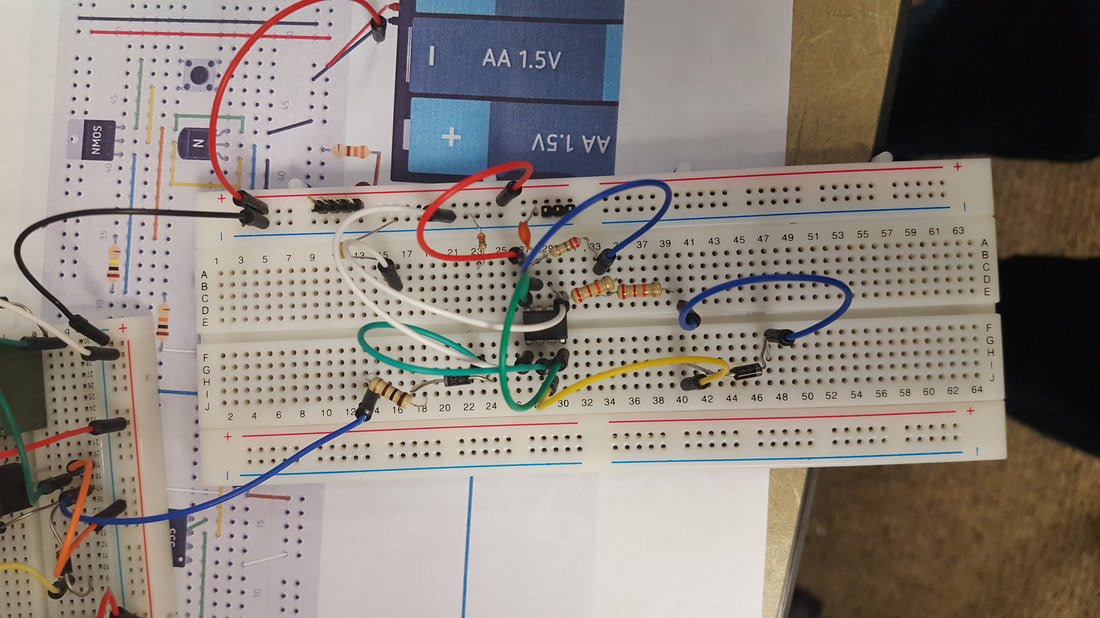
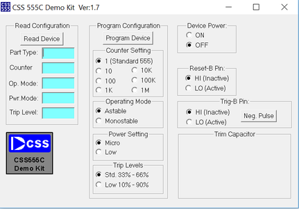
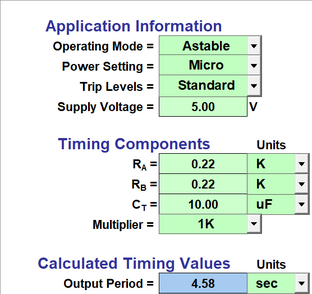
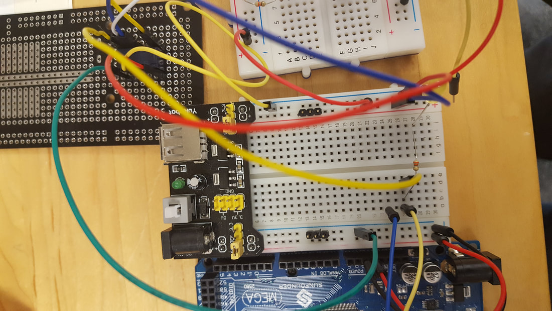
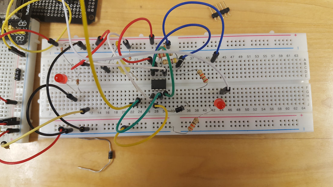
This week was all about setting up the timer chip on the circuit. The first thing I had to do was program the chip using the software to a small time frame (5-10 seconds) to make sure that the circuit was working. At first my mentor and I were unable to turn on the led no matter what we did. So we went about changing things about the circuit before realizing I had used the wrong resistor in my calculations. After fixing this the led still would turn on so we switched it was another one and finally the led turned on for half a second and then flashed off. We kept messing with the circuit but we unable to get the led to stay on for the time frame we needed. I went back to check the math to make sure that I had everything right however I had misread uF as nF on the capacitor. I quickly changed this and after this had the led staying on for the correct amount of time.
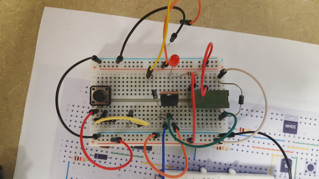
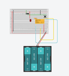
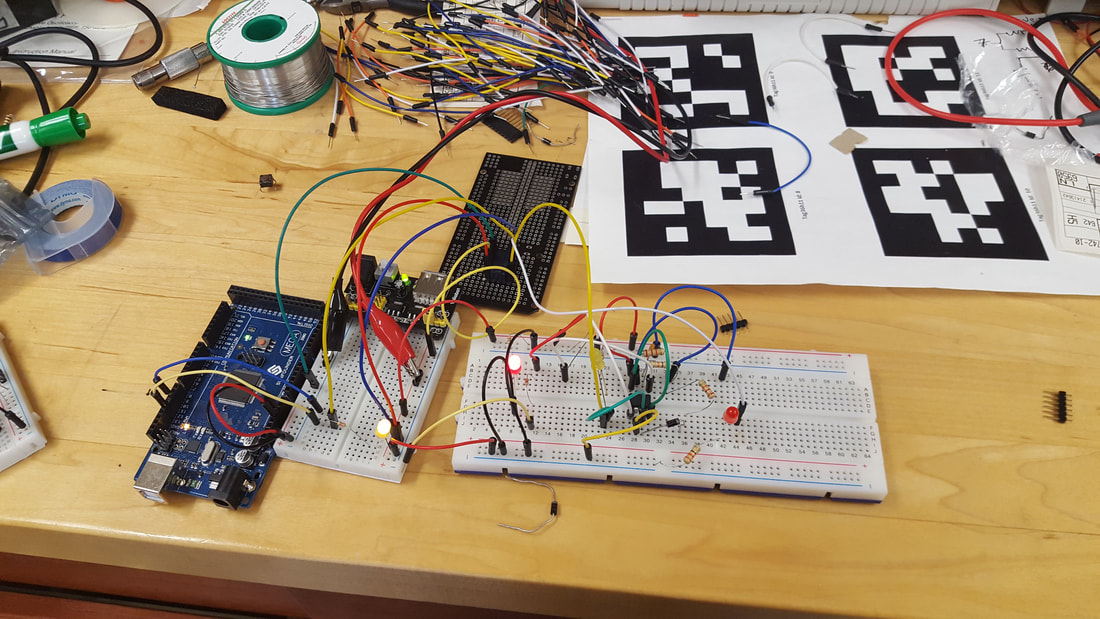
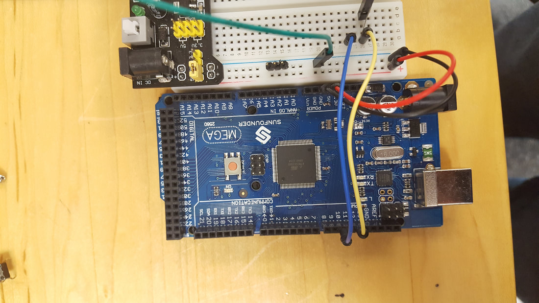
This week I worked on the second half of the circuit dealing with the relay. At first I built a relay based on one that Dr. Anderson had asked me to look at. However when I was trying to recreate the circuit online nothing was happening. When I went back to the original I got an error running it and then when I it finally did run nothing also happened. Frustrated I went to work on learning about working with the Arduino to learn how to program with it. After doing some of the tutorials I found online I realized that on the circuits online were backwards (the anode was grounded instead of being connected to power and the cathode was not grounded). When I fixed this everything clicked into place except for that the transistors we I had were different than the ones online. But after some googling around I was able to work around that. When I showed my results to Dr. Anderson, she said that we need something like this circuit except with out the transistor, needed to use the timer and the arduino to turn things off and on, and using the relay and not using the arduino for power. I was able to model what she wanted using a battery for power and using switches as the arduino and timer chip.
Week 6
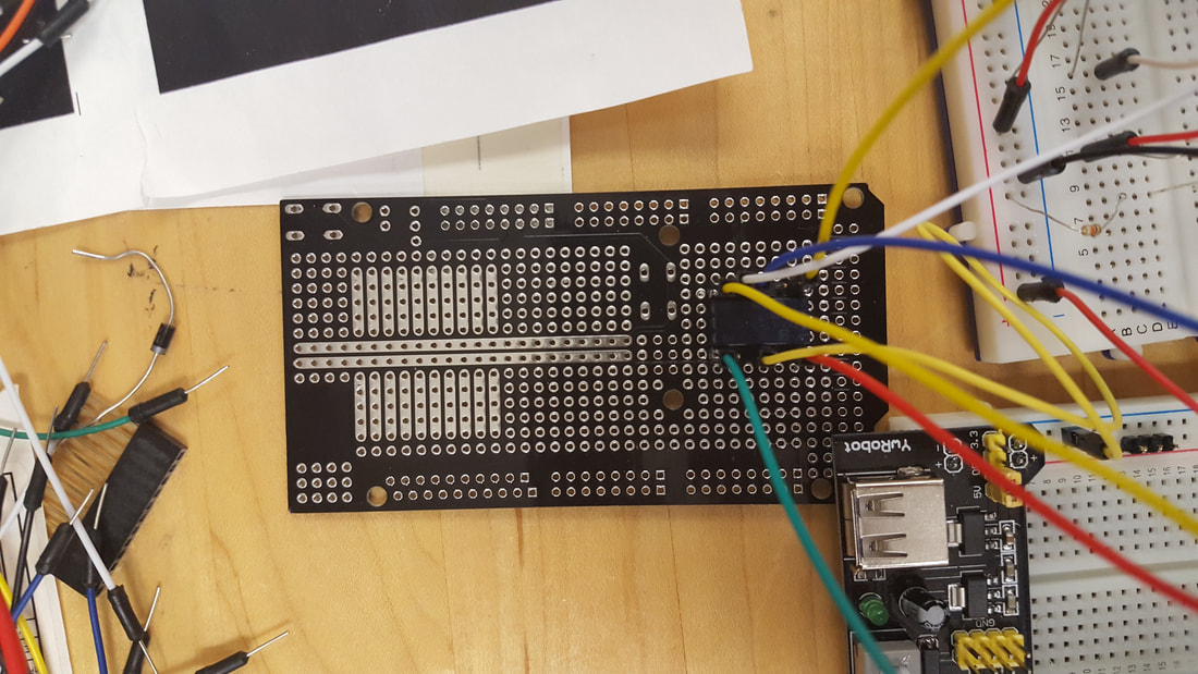
The first thing that happened this week was that I had to learn how to solder because the relay chip that we were now using could not fit the conventional bread board. I did manage to solder the relay to a solder board and make sure that it was properly before moving on to set up the relay. The next problem that I ran into was that this relay was not the one I used in my modeling but was a latching relay which meant that to switch which from normally open to normally closed you had to switch which direction power was flowing through the coils. This took some trial and error to find this out as when I originally hooked up the circuit the relay responded but would not respond on subsequent times. It was only when I got it to respond a few more times did I realize that I had been energizing the coil in random and not having positive always on one side. Then i found out that the relay actually had two coils which led to me making a circuit that was able to use the relay to turn on the arduino and have the ardunio turn itself off. However because of the way the circuit was wired the Ardunio could not turn it self off if the timer was still on and vise versa. This could pose a problem as if the timer or the arduino were to desync then either the arduino would die faster than I should or the would be a time frame where no data would be collected. We were able to come up with a proposed design where we would wire the left sides of the coils together and right sides together. This week we were also able to test the UAV project with a few people and I was able to help record the data however most of week was spent working on the circuit.
Create a free web site with Weebly
