Real-time Motion Capture
The main goal
is to capture real time human data and apply it to computer-generated
characters. The characters are modeled in Maya and animated using incoming
data from the motion capture system.
What is Motion Capture?
Motion Capture is the process of capturing the
movement of a real object in 3D space and mapping it onto a computer
generated object. The result is a computer character that moves exactly like
the real object. Usually, Motion Capture is used to capture the motions of
humans.
How does Motion Capture work?
For ìopticalî motion capture, a series of
high resolution cameras with special strobe lights are set up around an area
to be ìcaptured.î Small spheres (markers) covered with a
retro-reflective substance are placed in strategic locations on the person
(or object). Specialized software will locate the markers seen through
the cameras. The markers are then recorded as 3D coordinates (xyz). The
collected marker data over time creates motion data.
What is real time Motion Capture?
There are two types of motion capture:
offline and online (real time). In the case of the offline, the data is
captured, stored, processed (cleaning data from noise is common) and then
later applied to the computer character.Ý
However, in real time capture the motion data is captured and applied
to the character simultaneously. Depending on the capture system, there
should be no noticeable delay in the characterís movement compared to the
movement of the real subject.
A common problem with real time motion capture
is the presence of noise. If you plot the motion data you will notice that
the curves arenít always smooth, there are some unsettledness or jerkiness.
There are many filtering systems and techniques to eliminate the ìbad dataî.
During offline capture, one can go back to the data and ìclean it upî before
applying it to the computer character. But how about real time capture?
. . . Stages of Work . . .
 Ý Stage 1: Understanding how motion
capture is done Ý Stage 1: Understanding how motion
capture is done
The first step was to
familiarize myself with the motion capture lab and learn about conducting a
motion capture session. I attended one of the capture sessions and went
through a basic tutorial of how to work the equipment and what are the
necessary steps in capturing a motion. Here are the basic steps:
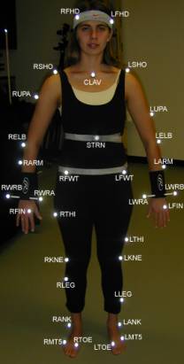
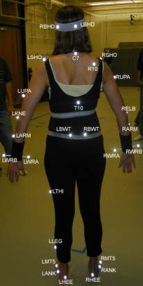
- Marker placement: Using the marker placement
guide, markers are placed on the subject(s). For humans there are either
40 or 41 markers total. Placing markers requires some practice, if some of
the markers are not in their ìexpectedî positions then that will result
in generating bad data later on.
Ý
- Calibrate the cameras: there are a total of 12 cameras
in the lab. This is necessary to make sure that all the cameras are able
to view the area used for capture. Basically a number of markers are
placed on the floor for ìstatic calibrationî and then a stick with
markers is waved around the area of capture, this is for ìdynamic
calibrationî.
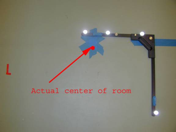 ÝÝÝÝÝÝÝÝÝÝÝÝÝÝÝÝÝÝ ÝÝÝÝÝÝÝÝÝÝÝÝÝÝÝÝÝÝ 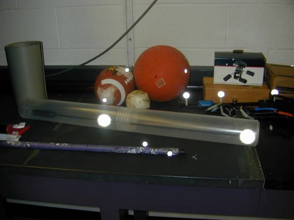
Calibration
AxisÝÝÝÝÝÝÝÝÝÝÝÝÝ ÝÝÝÝÝÝÝÝÝÝÝÝÝÝÝÝCalibration Stick
- Subject calibration: the subject of capture is
calibrated. For human capture, the person would stand in a ìTî position
with the arms straight out for ìstatic calibrationî and then the person
would do a simple motion such as walking across the room for ìdynamic
calibrationî.
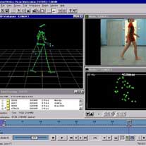
- Labeling: using the software ìWorkstationî,
you can view the captured motion as a collection of markers moving over
a period of time. Next step is to label the markers. Itís simply a
matching game, you are given a list of default marker names and you are
to match those names to the corresponding markers on the body.Ý Workstation will then connect the
markers to create segments.
(photo
from the Vicon website)Ý
ÝÝÝÝÝÝÝÝÝÝÝÝÝÝÝÝÝÝÝÝÝÝÝÝÝÝÝÝÝÝÝÝÝÝÝÝ ÝÝÝÝÝÝÝÝÝÝÝ
ÝÝÝÝÝÝÝÝÝÝ
- Ready to Capture: All the preprocessing is
complete and you are ready to capture. Simply click on the start button
and Vicon starts capturing the data.
ÝÝÝÝÝÝÝÝÝÝÝÝÝÝÝÝÝÝÝÝÝÝÝÝÝÝÝÝÝÝÝÝÝÝÝÝÝÝÝÝÝÝÝÝÝÝÝÝÝÝ
Ý Stage 2: Writing a plugin for Maya
ÝÝÝÝÝÝÝÝÝÝÝÝ The captured data
from Vicon will be applied to a computer character generated in Maya. Maya
is a 3D modeling and animation software. In order to apply the real time data
to the character, there must be some type of a link or communication method
between Maya and Vicon. This part of the project involves writing a plugin (
an additional program that enhances the features of an existing program) that
will allow Maya to receive data from Vicon.
Ý
ÝÝÝÝÝÝ Writing the plugin requires a good
understanding of networking concepts, an in-depth knowledge of how data is
handled by Tarsus (a Vicon software used for motion capture) and how Maya
maps incoming data to objects. This project seemed to be heavily involved
since I didnít know much about networking, Tarsus or Maya. Luckily, I was
able to contact the people at Vicon and they told me that they had already
written a plugin for Maya and that theyíll e-mail a copy to me.
ÝÝÝÝÝÝÝÝÝÝÝÝÝÝÝÝÝÝÝÝÝÝÝÝÝÝÝÝÝÝÝÝÝÝÝÝÝÝÝÝÝÝÝÝÝÝÝÝÝÝ
Ý Stage 3: Modifying the plugin
ÝÝÝÝÝÝÝÝÝÝÝÝ This is the general idea of how
data is communicated between Tarsus and Maya:
1.
Tarsus outputs data using named channels. Channels
are strings of double values varying over time. Each channel corresponds to a
specific source that could be either a marker or a body segment. In turn, the
plugin creates channels (vectors) to store the incoming channel data. coming from
the Tarsus channels.Ý
2.
The data stored in the vector channels is parsed,
modified and sent out to Maya using routines in the Maya server library.
Tarsus data
consists of the position(x,y,z) and orientation (qx, qy, qz ) of the body parts for the real time subject and the
position (only) of the corresponding markers. However, Tarsus doesnít provide
joint angle data, which is what we need. Therefore, the code must be modified
to extract joint angle information from the available position/orientation
data.
ÿ
Calculating
joint-angle information:
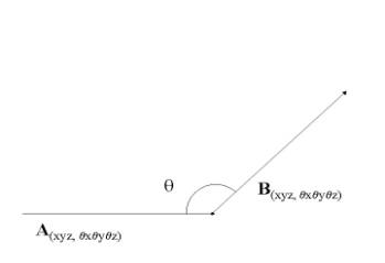
ÝÝÝÝÝÝÝÝÝÝÝÝÝ Given
the position and orientation of two body parts we can calculate the angle for
the joint joining the two bodies using quaternions. A quaternion is a 4-tuple
of real numbers [s,x,y,z] or [s,v], s is a scalar and v is a
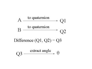
three-dimensional vector.Ý First,
represent the position/orientation data of both body parts as quaternions,
find the difference of the two quaternions and the result is the angle for
the joint
connecting the two body parts.
|
|
A , B = a 6-dimensional vector with the center at
(x,y,z) and orientation at (qx, qy, qz ).
|
ÝÝÝÝÝÝÝÝÝÝÝÝÝÝÝÝÝÝÝÝÝÝÝÝÝÝÝÝÝÝÝÝÝÝÝÝÝÝÝÝÝÝÝÝÝ
Ý Stage 4: Modifying the Vicon files
ÝÝÝÝÝÝÝÝ Part of the Vicon system are files
called .MKR and .KM files, they contain lists of: 1) marker labels, 2) body
segments and their corresponding markers. By default, the marker file (.MKR)
for a human contains 40-41 markers and the kinematic model file (.KM)
contains 17 body segments. Ý
ÝÝÝÝÝÝÝÝÝÝ A typical human
skeleton file contains around 30 body parts, which adds more degrees of
freedom to the body and results in a better looking motion. To match with the
current skeleton files being used, the marker and kinematic model files need to
be modified to include more body segments. Both files can be viewed as text
files and to change the number of segments requires typing in few additional
text lines.
|