Week 3 : Parameterized FPU

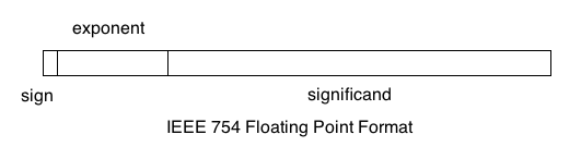
Now that the FPU worked with 32 bit numbers, it needed to be modified to allow for IEEE-754 double precision (64 bits) and IEEE-754 half precision (16 bits). The solution I used was to try and parameterize every line of code that contained hard coded bit lengths. Screen Shot 2017-07-07 at 3.04.27 PM

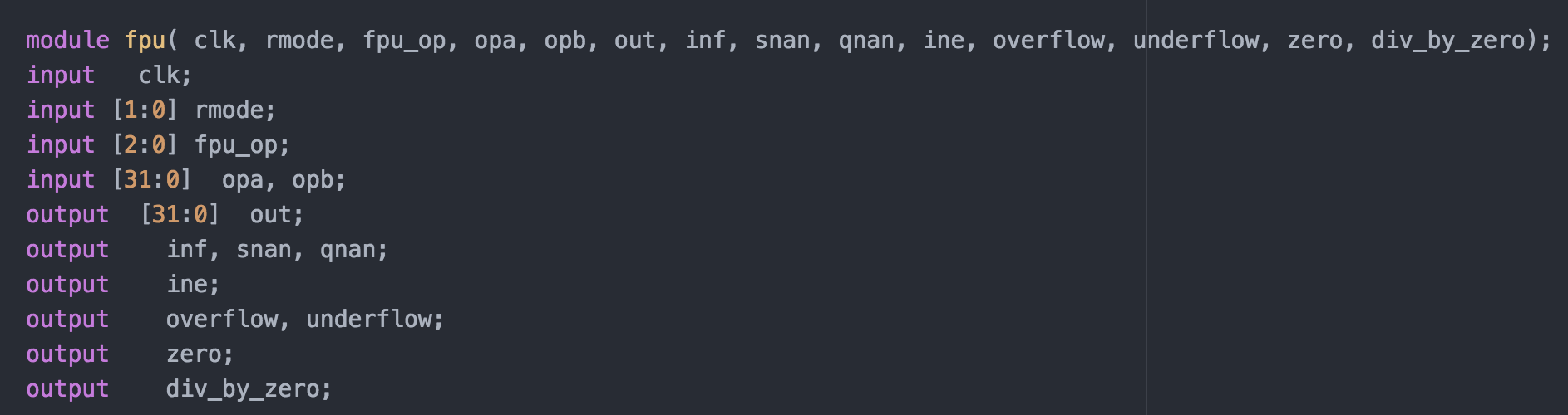
Before Parmeterization

Screen Shot 2017-07-07 at 3.04.46 PM
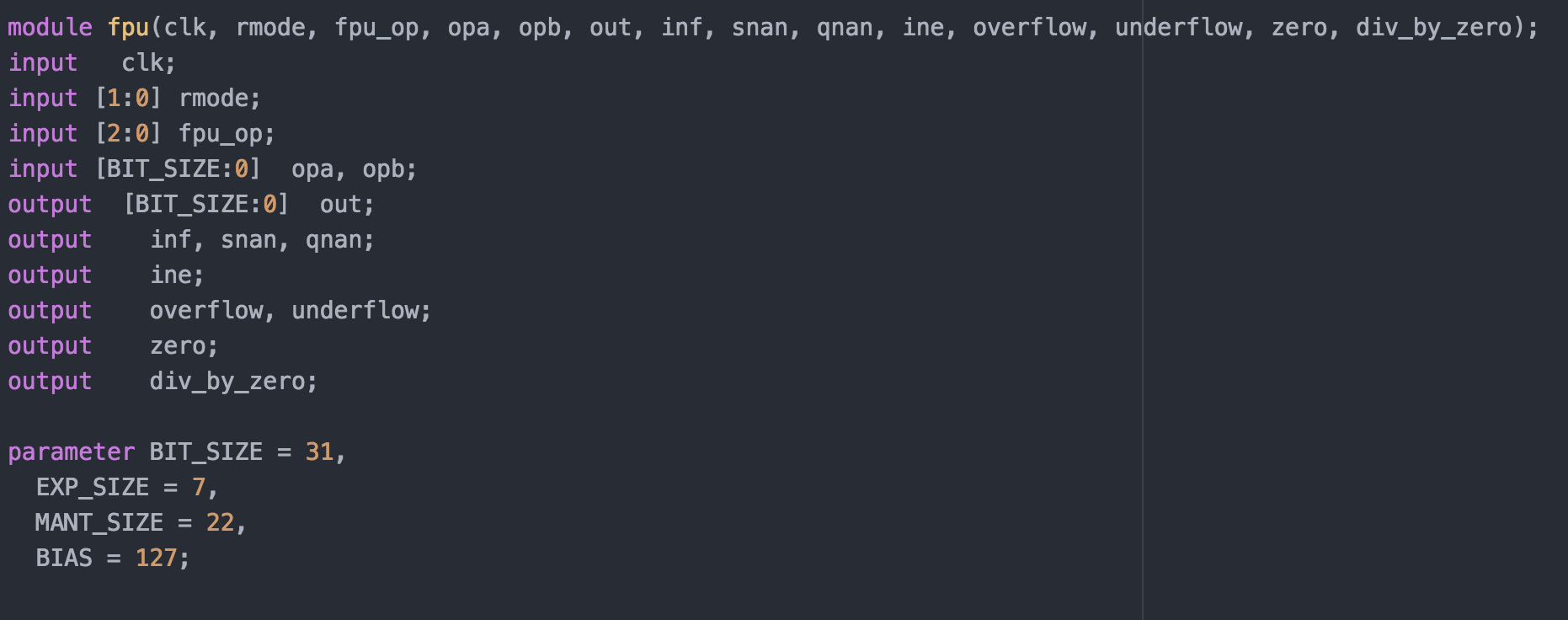
After Parameterization

By changing hard coded values throughout the source to parameters, I should be able to affect the input and output precision of the FPU. I spent the rest of the week going through every line of code, testing different values, and modifying the parameters accordingly. Since verilog starts indexing bit arrays at zero, I subtracted one from each of the actual values needed in my parameterization, which made the resulting code a little bit easier to read.

Week 2: Getting Started with Floating Point

This week, to better understand the floating point module, I was tasked with developing a way to test the module’s functionality. However, before I accomplish this, I needed to have a thorough understanding of how floating point numbers are represented inside a computer. At this time, pretty much every piece of hardware follows the IEEE-754 standard for representing floating point numbers. In the 32 precision standard, one bit is used to represent the sign, eight bits are used to represent the exponent, and the remaining 23 bits are used to represent the mantissa. Since negative exponents also need to be represented, the value of the exponent is subtracted by 127. More information on IEEE-754 single precision can be found on Wikipedia. An example of the representation is shown below.

Unfortunately, the test vectors provided in the source did not function, so I needed to find a way to test the module myself. In the program IEEE_number_gen, I created a way to generate random bits, then convert them into the correct IEEE-754 floating point format. The program can also convert an input into IEEE format and numbers in IEEE format into floats. After thorough tests, the module seemed to function as intended.

Week One: Getting Settled In

After landing in the Chicago midway airport on June 4th, I took the train to Evanston. Due to a miscommunication with my landlord, the apartment I would be staying would not be ready for me to move into until the end of the day. This gave me an opportunity to explore Northwestern’s campus. The first place I visited was Dr. Joseph’s office, so I would know where to be the next morning. Leaving the tech building, I was confronted with a stunning view of Lake Michigan, and a beach crowded with students. After exploring Evanston for a few hours, I could finally move into the apartment.

The next day, I woke up at 8, ate breakfast, and headed over to the Tech building. This was the first time I met Dr. Joseph in person, he brought me into his office and we began discussing the project. The main purpose of the project is to test and benchmark a floating point unit, and see where errors occur. Instead of building a FPU from scratch, we utilized an OpenCores project as a framework to save time. Before any testing could be done, I needed to create a way to easily test the hardware, and before that, I needed to fully understand how the hardware worked. I spent the rest of the week going the the source, and taking note on the entire calculation process.