At this point, I have collected and saved almost all of the data I need to write the report. However, I also wanted to do the same bit level analysis I did of the 32 bit FPU to the 64 bit FPU. However, I estimate the time it will take to collect this data will be at least two days. While that script is running, I have started outlining and writing the report. I am also reorganizing the work I have done, as well as writing a much more verbose documentation for the graduate student taking over the work I have done.
Week 9: Data Collection
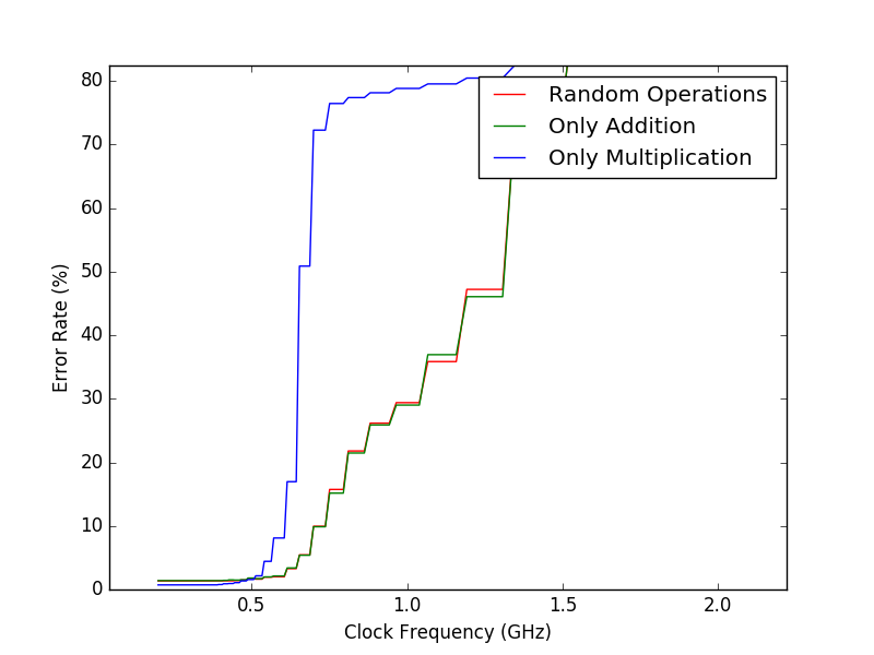
Over the weekend, I had the server run the experiment with three different test vectors: only addition, only multiplication, and a mixture of both. When I got back to the lab, they had all completed. Using the pyplot library, I could plot the results on a graph pretty easily. Below are the preliminary results:

A graduate student is planning on continuing the research I am doing, so I spent a majority of this week explaining the work I had already accomplished and how all of the scripts work. In addition, I set up a workflow automated the data collection aspect of the 64 bit FPU experiment. I also wanted to analyze which bits of the output generated the most error, so I created a better tool to analyze the data. This too will take a while to finish, but it is all automated. Once these processes finish, I will have everything I need to start writing the report.
Week 8: The Experiment Begins
Now that the the gate level simulations and timing reports were collected, the experiment could now begin. To accomplish this, I used my previously created test vector generator, along with a new script created to that could compare the results calculated in python with the output generated by the verilog simulation of the hardware. I also create a script that allowed me to compile the hardware at a given clock period, thus changing the clock frequency. Combining all of these scripts, I could begin the experiment. Varying the clock frequency, I collected the error rate of the hardware and plotted them on a graph. However, generating these results took days, so I should have most of the data collected by next week.
Week 7: Timing
Over last weekend, I had the computer compile a gate level design for each bit width: 64 bit, 32 bit and 16 bit. When I arrived at the lab on monday, they all had compiled. Once the gate level synthesis was complete, I needed to run timing analysis software on each design. This software would calculate the actual speed of data through each gate. With this information, we will be able to tell if there is any timing errors in the design, as well as simulate the real world response of the hardware. To accomplish this, I utilized some python code from a project of a previous graduate student, and modified it to analyze the gate level designs of each bit level floating point unit. After its completion, I received output files for each piece of hardware. Inside, was a detailed list of every gate, along with the time in nanoseconds it took to process data. While this worked for the 64 bit and 32 bit versions, I could not generate timing information for the 16 bit FPU.
Week 6: More Debugging
Now that all of the code was migrated over to the remote server, I could now convert the verilog into a gate level representation of the hardware. To accomplish this, I modified some code by previous graduate students, to compile the verilog. Before compiling my modified design, I attempted to synthesize the gate level design of the original verilog code. However, I was greeted with multiple errors. One of the first issues that arose, was that division could not be implemented at all. Secondly, many of the hard coded values that were used in the process of denormalization crashed VCS. Once I fixed the errors in the original design, I had to do the same for my modified version. However, even after implementing the changes of the original, my modified design still did not work. VCS would not allow me to synthesize a design that had varying bit widths. To fix this, all I had to do was change the design from a parameterized version, to a `define macro based version. Once I completed that, I could synthesize a gate level design.
Week 5: Gate Level Synthesis
Since the 4th of July was on a Tuesday. I got Monday off. This gave me the opportunity to visit my family at home. When I got back to Northwestern, I began the second phase of the project. Now that we had a parameterized version of the FPU, we could now use a tool called Synopsys Design Compiler to synthesize a gate level design of the code. To accomplish this, I had to migrate all of my code to a school-run server that had the software installed. In my testing, I used Icarus Verilog to compile the design. However, to get a more accurate response of how the module behaves, Synopsys’ VCS compiler needed to be used. VCS is a much stricter compiler, and the same source code that gave me no warnings in Icarus Verilog gave me hundreds of errors in VCS. So most of this week was spent on trying to get the working source code to compile under VCS.
Week 4: Testing and Debugging
After changing every value in the source code to it’s parameterized form, it was still full of errors. While the 32 bit parameter worked, the 64 bit and 16 bit versions still did not compile. This was do to the fact that original source contained logic that could not be parameterized. In the IEEE floating point standard, when rounding a number, a single bit is used to determine whether the bits following the cut off point is greater than one. In the implementation that we are using, every possible place the one could be is tested in a case statement. To fix this for the 16 bit and 64 bit implementations, I had to create separate code to check the bit precision, and run the necessary code. In addition to these specialized case statements, I had to come up with a formalized way of testing the code. Up until then, my tests were ad hoc, just to make sure that I was getting a proper result. Changing this, I wrote a python script that would generate random IEEE floating point numbers, and run a random operation on them. The result would be calculated by both python and the verilog FPU. From that, I could compare the values obtained, testing the functionality of the FPU. Once the FPU was up and running, we were finally able to move on to the second phase of the project.
Week 3 : Parameterized FPU
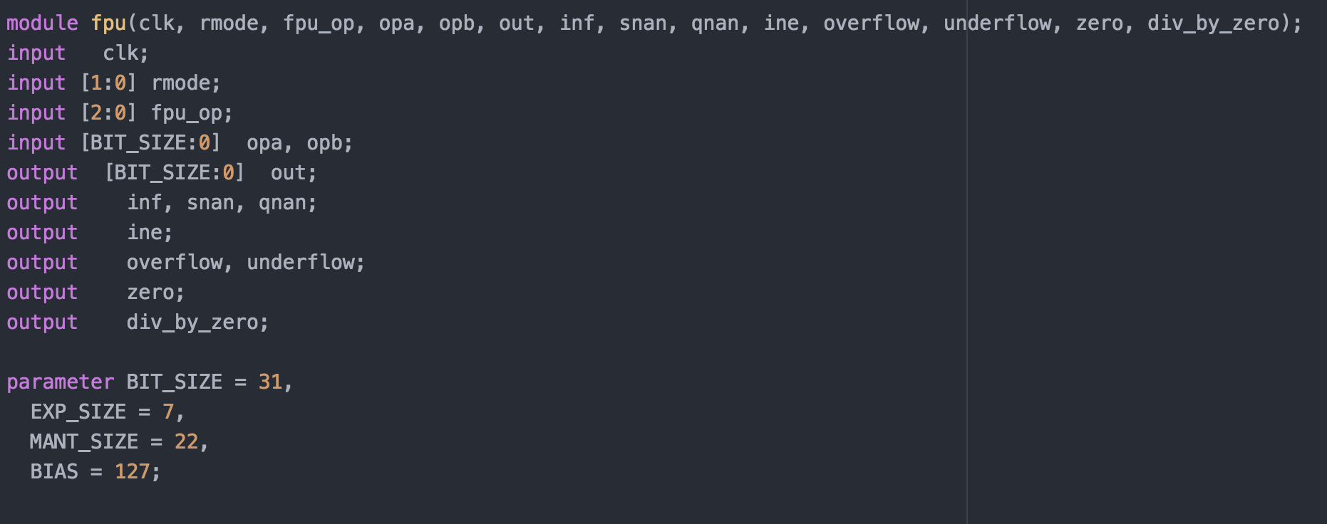
Now that the FPU worked with 32 bit numbers, it needed to be modified to allow for IEEE-754 double precision (64 bits) and IEEE-754 half precision (16 bits). The solution I used was to try and parameterize every line of code that contained hard coded bit lengths. 
Before Parmeterization
 After Parameterization
By changing hard coded values throughout the source to parameters, I should be able to affect the input and output precision of the FPU. I spent the rest of the week going through every line of code, testing different values, and modifying the parameters accordingly. Since verilog starts indexing bit arrays at zero, I subtracted one from each of the actual values needed in my parameterization, which made the resulting code a little bit easier to read.
Week 2: Getting Started with Floating Point

This week, to better understand the floating point module, I was tasked with developing a way to test the module’s functionality. However, before I accomplish this, I needed to have a thorough understanding of how floating point numbers are represented inside a computer. At this time, pretty much every piece of hardware follows the IEEE-754 standard for representing floating point numbers. In the 32 precision standard, one bit is used to represent the sign, eight bits are used to represent the exponent, and the remaining 23 bits are used to represent the mantissa. Since negative exponents also need to be represented, the value of the exponent is subtracted by 127. More information on IEEE-754 single precision can be found on Wikipedia. An example of the representation is shown below.

Unfortunately, the test vectors provided in the source did not function, so I needed to find a way to test the module myself. In the program IEEE_number_gen, I created a way to generate random bits, then convert them into the correct IEEE-754 floating point format. The program can also convert an input into IEEE format and numbers in IEEE format into floats. After thorough tests, the module seemed to function as intended.
Week One: Getting Settled In

After landing in the Chicago midway airport on June 4th, I took the train to Evanston. Due to a miscommunication with my landlord, the apartment I would be staying would not be ready for me to move into until the end of the day. This gave me an opportunity to explore Northwestern’s campus. The first place I visited was Dr. Joseph’s office, so I would know where to be the next morning. Leaving the tech building, I was confronted with a stunning view of Lake Michigan, and a beach crowded with students. After exploring Evanston for a few hours, I could finally move into the apartment.
The next day, I woke up at 8, ate breakfast, and headed over to the Tech building. This was the first time I met Dr. Joseph in person, he brought me into his office and we began discussing the project. The main purpose of the project is to test and benchmark a floating point unit, and see where errors occur. Instead of building a FPU from scratch, we utilized an OpenCores project as a framework to save time. Before any testing could be done, I needed to create a way to easily test the hardware, and before that, I needed to fully understand how the hardware worked. I spent the rest of the week going the the source, and taking note on the entire calculation process.