I arrived Providence, RI on Tuesday, June 1. Since it was late, Wednesday, was practically my first day at work. I met Dr. Chad Jenkins,
the postdoc researchers and PhD students at the lab and I was assigned a computer.
Later that day, I had lunch with Dr. Jenkins where
I was introduced to the kind of research that goes on in the RLAB and what I should expect. Back at the lab, for starters, I was given an Asus Eee PC
without ROS (Robot Operating System) installed on it and I had to install it using the tutorials on the website
http://code.google.com/p/brown-ros-pkg/.
With that installed, the next step was to learn how to use/understand ROS commands. So, I got started on the
ROS tutorials.
Outside of work, sometimes I just walked around to see the city for myself. Providence is a nice small city.
WEEK 2 [June 8 - June 14]
I continued working on the ROS tutorials. After much reading, I ran some of the sample C++ codes that were made for
the iRobot Create.
Sample program - spin around at 0.4rad/s on one spot until you exit. It was a ROS node written in C++.
In the program, these parameters gave the robot such behavior:
x (linear-x velocity) = 0.0, y (linear-y velocity) = 0.0 and z (angular velocity) = 0.4
It was a very very basic program just to get started with creating ROS nodes.
I modified this program to do other things just to get used to the platform.
Outside of work, I realized that my apartment is close to the gym and that became my second port of call on most evenings after getting off work.
WEEK 3 [June 15 - June 21]
At this point, I had become fairly familiar with the basic ROS packages. It was time for my first assignment.
I had to write a ROS node (programs are called nodes) that will subscribe to a camera's images
and save pictures at intervals.
To write this program required 3 additional tutorials - An Overview of OpenCV (Open Source Computer Vision); How to convert
ROS images to OpenCV using CvBridge; and How to save an image from a stream of OpenCV images.
Using the tutorials, I completed a program that will get images from the images from the camera, convert the ROS images to OpenCV IplImages
using cvbridge, display that on the screen and save.
WEEK 4 [June 22 - June 28]
At this point my ROS node has its basic features, but I just added some new features to it:
Create new directory using name specified by user (or use default as the current time when the program is run) where the pictures for each session will be saved.
Easy saving by incrementing file names - pic1, pic2, ...
Set intervals for saving picture frames
In doing these, I also learnt about rosparam which allows you to store and manipulate data on the ROS Parameter Server.
This made the program more flexible for the user. In the next step, I'll use this program.
WEEK 5 [June 29 - July 5]
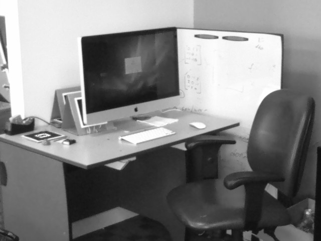
At this point, my node is ready for use. My task now is to mount the camera on the iRobot Create robot and then drive towards the
ball from different angles while taking pictures of the ball as it approaches. I was to do it for different places with different lighting conditions
so that we can have a good database of pictures for the training.
Since I had two different programs to be run (one to drive and the other to take pictures), I created a .launch file that can
execute all the nodes and their dependencies at the same time.
With this, I was ready to go. So, I took the ball out and ran my drive_n_snap.launch.
With these pictures saved, it was time to start working on them in other to do the actual training
because all we've been doing is to try and see the ball from the perspective of the robot.
WEEK 6 [July 6 - July 12]
This week, my task was to create a program that will be used to "manually" locate the ball in the picture by finding its center (x, y)
and radius in each of the pictures. The simplest approach is to circumscribe the ball with a circle and then record the center and radius of the circle.
This required a good knowledge of OpenCV and HighGUI (High Level Graphical User Interface). The latter is the GUI for OpenCV
where one can interact with images using the keyboard/mouse. To get into it, I had to get back to the OpenCV textbook. Reading took up most of the week.
After trying out and modifying some sample programs, I had understood enough to implement mine.
My first idea was to left-click on a "tentative" center of the ball and right-click on any point on the circumference of the ball.
When this is done, the distance between the two points becomes the radius of the circle. This is then used to draw the circle.
This did not always come out well as one may not click on the accurate center of the ball.
My second idea worked better - using the mouse to drag a circle around the ball. Basically, LButtonDown records the initial
position p1 in a cvPoint() object; while it's still down, MouseMove records new position p2; finally, LButtonUp
records the final p2 when user releases the button. The Math involved: the distance between p1 and p2 is the diameter;
using pythagoras theorem, radius = (sqrt((p2.x - p1.x)^2 + (p2.y - p1.y)^2))/2;
and the center is halfway through the two points, which is ((p1.x + p2.x)/2, (p1.y + p2.y)/2). These values are then passed to the cvCircle
function to draw the required circle in real time.
That was it for my "locate ball" program. Now I need to use it to get the position information of the ball in all the pictures that I took earlier.
Drag a circle around the ball. Observe center (x,y) and radius R.
's' - save circle info to a text file
→ - load next image
← - load previous image
'Spacebar' - clean up mistakes on a picture
'Esc' - Exit
WEEK 7 [July 13 - July 19]
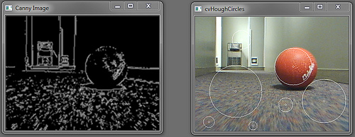
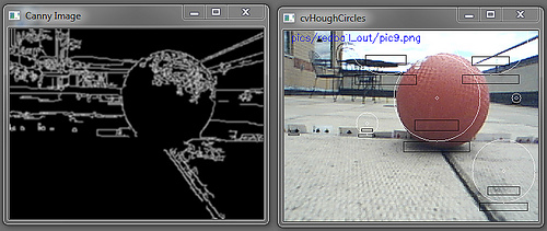
This week, I was trying to use Hough Transforms to detect a ball in an image.
OpenCV contains a function called cvHoughCircles that detects circles in an image.
Based on the assumption that a ball is potentially a circle on the 2-D image, I tried using this to
to find the ball in an image. To do this, Canny Edge detector is used to convert the
image into a format that makes the circles in the image more obvious.
In this example, the ball is detected amognst many other false positives. These could be reduced by altering the
cvCanny parameters.
WEEK 8 [July 20 - July 26]
This week, I was trying out the template matching. The template was a cropped-out ball from the reference picture.
In this case, the template was found. I also tried it with a smaller size of the same template but this gave a false positive.
This suggests that we need a scale-invariant method.
WEEK 9 [July 27 - Aug. 2]
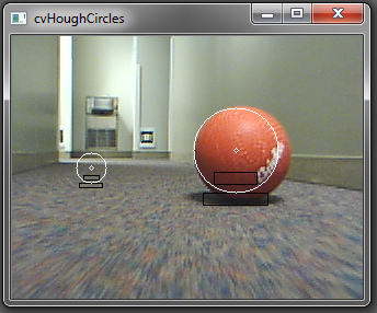
After reading some papers, I came across an idea to reduce the number of false positives - shadow detection.
I developed a section of code to compare the average pixel value of a rectangular area underneath the circle
(where a shadow is expected to be if it’s a ball) with the average pixel value of a rectangular area in the
circle somewhere below its center. If a shadow exists, the former will give a lower pixel value, based on the
fact that darker colors have a lower pixel value and brighter colors have a higher value. The figure below illustrates the attempt.
It worked for this image. Result:
WEEK 10 [Aug. 3 - Aug. 9]
This was my last week and I had to conclude my research and start writing the final paper. Before that, I had to make sure
that the {Hough Transform + shadow-detection} technique works well with other test images in our database.
It turned out the success rate was low. (LOL)
There are two main reasons for such observation:
The backgrounds in these images have an uneven color. Therefore, one can detect a darker section which is not actually a shadow.
The ball was not detected as a Hough Circle. The rate of success of accurately detecting a
ball as a circle (even if it includes false positives) was quite low.
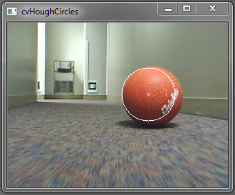
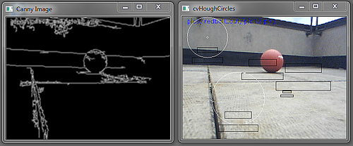
In this example, due to uneven background colors, the shadow detection was not sufficient in eliminating all the false positives.
In this example, the shadow detection was unnecessary because the ball was not among the circles detected by the
Hough Transform circle detection technique. Since none of the circles was a ball, searching for shadows was irrelevant.
This was the case for most of the images.
The Hough Transform is not a very efficient method for detecting a ball. But if the ball is detected (among other false positives)
and the image background is even (or almost even), shadow detection could be used to eliminate some of the false positives.