1. Introduction
This summer I worked at the University of Minnesota under the guide of
Professor Victoria Interrante on a project known as GL Creator. GL
Creator is actually a collaboration between Professor Interrante and
Professor Lee Anderson of the Architecture Department at UMN. Graduate
student Joseph Cherlin has also worked closely with this project. GL
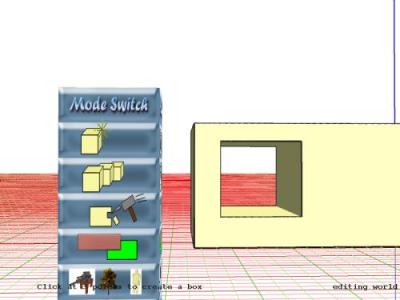
Creator is a computer program created to allow architectural students to
design structures in a virtual reality (VR) world. The consequences of
this VR interface is that the designer is able to walk around and
thoroughly inspect their three-dimensional creation. It is to be
determined whether GL Creator has a significant impact on the type of
structures architectural students design.
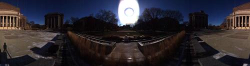
My research this summer was to add a three-dimensional backdrop to GL Creator. Another concurrent project under Professor Baoquan Chen involved a panoramic laser scanner. My project was to take the data from a scan of the Northrop Mall, break the image into strips based on the range information provided, and map the pieces onto concentric cylinders with closer objects appearing on the inner cylinders. Consequently, a viewer positioned in the center of the cylinders would have the impression that foreground and background objects are independent, thus giving the illusion of three-dimensionality.
2. Implementation
The implementation of the 3-D backdrop can be broken down into five phases: formatting the data from the scan, creating the sphere object, texture mapping, breaking up the image with transparency, and touching up the images.|
 2.2 Creating the SphereOnce the pixel information was formatted the way I needed, I went on to create the sphere object. Instead of having a cylinder, Vicki thought it best to use spheres with the tops and bottoms left open (i.e., chopped off). She also advised me to create my own sphere object instead of using OpenGL’s predefined sphere function. The approach was a facet approximation of a sphere, where the sphere is actually made up of many four-point facets, or quadrilaterals [1].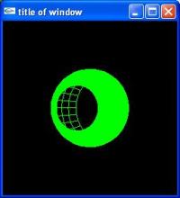 2.3 Texture MappingWith the sphere created, the next step was to texture it with the Northrop Mall image. Texture mapping required me to pass in the texture coordinates for each quad as a number between 0 and 1 as well as the size of the texture. Because the size of the texture must be a perfect power of 2, and the next power of 2 large enough to accommodate the image was too big as a parameter for openGL’s texture binding function, I could not keep the resolution of the image as one texture. Therefore, it was necessary to split the texture into three pieces and scale the coordinates accordingly.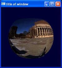 2.4 Working with the Range Data and TransparencyOnce one textured sphere was working properly, it was now time to create multiple spheres with a different strip of the image on each sphere. Segmenting the image based on the range information proved to be a more complicated task than expected. In the end, the image could only be broken into 3 pieces to remain convincing: the ground, the buildings, and the sky. Otherwise, segmenting the ground or parts of buildings, which should move as one unit, would look very strange. For the image breakup implementation, Vicki suggested a preprocessing approach. She recommended that my code that writes the image into a PPM file instead should output a separate PPM file for each strip of the image. For each file, only the strip that is to be textured onto a sphere will show up; the rest of texture will become transparent. Therefore, once textured, only the part of the sphere that is textured with the strip will be seen; the rest of the sphere will be completely transparent, leaving the viewer free to see the strip on the next sphere behind it.2.5 Touching Up the Image SegmentsAlong with the success of three textured spheres came several new problems. The first problem was that some pixels had no range information which resulted in scattered holes too numerous to ignore. The second problem also involved holes. As a user walks around inside the sphere, the 3-D effect comes from being able to partially see behind objects as he or she walks by them. However, as the original image was shot from a specific perspective, there will be no data for what is behind an object. A large hole will appear instead. The third problem was concerning the breakup of the image. To pinpoint a specific range value that would be favorable for every place along the strip was impossible. For example, if the cutoff was too small, then some tall bushes would become scattered between two spheres. If it was too large, the stairs of Northrop to the right of the bushes would be segmented. To lessen the impact of all these problems on a user, it was necessary to fill in all holes and other distractions in paintshop by hand.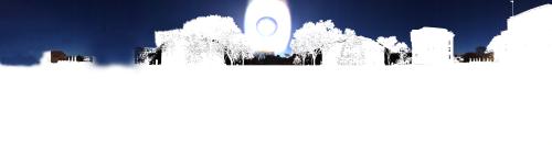 |
3. Conclusions and Future Work
When all was working in GL Creator with the final touched up versions of the images, my final opinion was that the 3-D effect of the backdrop was not so effective. As a user looking through the headmount, it still appeared to me that I was in a 2-dimensional world. The movement of the objects against one another between spheres was minimal. This may have been due to the viewing frustum setting of GL Creator, but I am not sure. I attempted to adjust the radii of the spheres, but it didn’t seem to have a significant impact. I found if the radii were too large, there appeared to be no movement at all, and if they were too small, the image would become too warped at the top. The trees were also very distracting. I wasn’t able to segment them perfectly, so parts of trees were divided between multiple spheres. The branches were also not perfectly separated from the sky, giving the trees a cutout look. A graphics graduate student suggested that perhaps instead of a PPM format I use one that allowed transparency values to be passed, which is something to think about for future work.In a virtual reality world, it is key that the user become completely immersed in that world; to be able to fool that this computer generated place is reality is a part of its purpose. Therefore, even the smallest inconsistencies can be enough to remind the user that this world is not real. Though I tried my best to cover up holes and distracting segmentations, it was not enough to create a convincing VR world. Until a way is found to rid the majority of these inconsistencies, I believe this method of a 3-dimensional backdrop will not be effective.