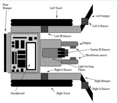
Figure 1: Robotic Schematic[2]
The first step in either communication or previous location storage is logically calculating the position of the robot. Since the robots were already built the localization algorithm had to ideally require few hardware changes and would work with the existing hardware. Therefore, method that took little storage space and had little run time was necessary. It was decided to calculate the position in respect to three lights much like the Space and Robotics Group at the University of Toronto Institute for Aerospace Studies. However, rather than using a Newtonian method which would take up a great deal of space and time we used a smaller, simpler algorithm which will be described in further detail in another section.
Data Acquisition and Processing
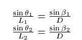
The first step in calculating the position of the robot is detecting the three lights. Two of the lights will be placed at the far corners of the arena. There will be no possible scenario where the robot is not in-between the two furthest lights. The other light will be placed directly in the middle of the two lights. The lengths will be measured and the robot will know the distance between each light. The total size of the arena is yet to be determined. To collect the data the robot stops and rotates its turret 360 degrees taking 120 samples (a sample every 3 degrees). The sensor reads values of 0 being light to 255 being dark. A sample of the type of data collected can be seen in Figure 2.
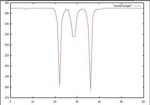
Figure 2: Example of collected data
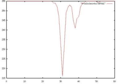
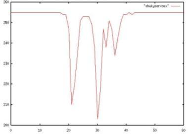
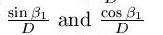
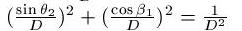
Extreme cases can cause the data to come out in such a way that three lights are not well defined. Some situations in which these extremes occur are when the robot is very close to a light, the robot is on one of the far sides of the arena, or if the servo, the motor used to turn the turret, shakes. Figure 3 shows data that was acquired from the far side of the arena. In this case the robot sees the light from the middle light and light furthest from it as being the same. To fix this problem a long tube was added to the photodetector in order to increase the resolution. Figure 4 shows data acquired when the servo was shaky. Here the robot sees more than three light spikes because the shaking of the servo has caused it to not smoothly detect the light values. Problems such as these must be dealt with so that a good data set can be collected.
 |
 |
After the data has been collected the three lights must be determined from the data. First a filter using the average light value is applied. Most of the values in the sample will naturally be dark because there are only three light points. Any spikes above this value were not considered because they were due to noise. Next the slope of the lines are calculated. A light is determined to be the point where the slope changes.
The last step is to take the three points and determine the angles between the middle light and each outer light. Before this can be done the it must be determined which light each point corresponds to. The robot will not always detect the left-most light first. An example of this is if the robot's back is directly facing the wall. It will start detection and pick up the middle light first, then the right-most light, and finally the left-most light.
Localization Algorithm
Once the three lights have been detected the robot is ready to calculate its location. Figure 5 shows the set up of the lights and some of the variable that will be used in this explanation. As has already been stated the robot will be between the two outer lights. The distances between the each outer light and the middle light are the same. The robot can be anywhere in-between these lights. The localization algorithm finds the robots x,y position. The y-coordinate is negative if the robot is "below" or to the right of the middle light and positive if it is "above" or to the left.
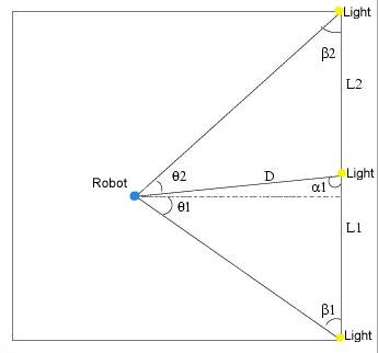
Figure 5: Diagram of triangle robot will use to calculate its position
Using the Law of Sines the following can be determined
 .
.We also know that
 .
.Substuting we find
 .
.We then solve for
 .
.We can then find D since:
 .
.The x and y coordinates can now be calculated
 .
.We now know the distance from the robot to the middle light.
Future Work
Now that the localization algorithm has been worked out future work will include tests to more accurately determine the accuracy of the algorithm. A method must be devised that will determine which direction the front of the robot is facing in respect to the lights. Radio communications must also be implemented. The radios that have been chosen are RF radios made by RF Monolithics. The effect of communication upon the search and retrieval task must also be evaluated. If communication takes too much resources or time it might increase the time needed to collect all of the targets.
References
1 Martin, .G. 1998. The Handy Board Technical Reference MIT Media Laboratory, Cambridge, MA.
2.Rybski, P.; Larson, A.; Lindahl, M.; and Gini, M. 1998. Performance Evaluation of Multiple Robots in a Search and Retrieval Task. ACM