|
Project Overview
This report includes a supplemental presentation
titled Human-Robot
Interaction: A
Straw Man approach to Interface Ite
ration -
The ARTV-Jr.
The original INEEL interface.
The first iteration of the UMass Lowell redesign.
The second iteration of the UMass Lowell redesign.
"
The final iteration of the
UMass Lowell redesign.
|
Machine:
To the left is an
ARTV-Jr. Robot produced by IRobot.
In
the past, IRobot spent time producing educational machines. The
company
made a decision to cease the educational/institutional robot
division due to consistent profit losses. Unfortunately, to that end,
IRobot provides no product support.
The original
ARTV-jr design has 14 sonars, emergency stop buttons mou
nted
on top of the machine,
a
brake,
and 4-wheel drive.
In addition to the basic specs ,
t
he UMass Lowell ARTV-Jr. is equipped with 10 additional sonars,
a wireless
connection, a laser, four cameras: one forward and one
rear both with pan tilt zoom and two stereoscopic front mounted
cameras, a Global Positioning System (GPS).
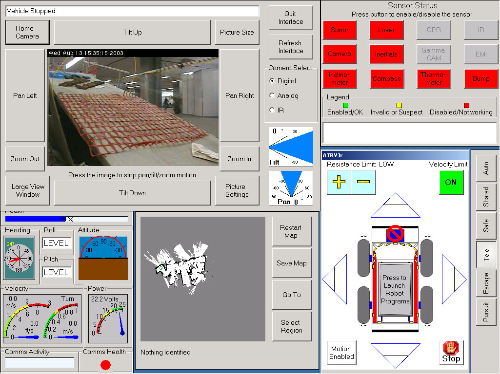
Interface:
Our team was charged with the task of
redesigning and reworking the
INEEL interface. We worked with a "Straw
Man", meaning, we used the INEEL inte
rface as a starting point
and applied
research principles from Urban Search and Rescue, Human-Robot Interaction,
and
Human-Computer
Interaction in order to modify the interface.
INEEL
is a government lab that, according to their web site, "
;strives
to deliver science and engineering solutions to the world's
environmental, energy, and security challenges." INEEL regularly
competes in the Urban Search and Rescue competitions held
at the AAAI conference. In 2003, INEEL won AAAI.
AAAI Competition:
Robots have twenty minutes to search
an urban disaster competition arena for simulated victims. The operator
commands the robot from behind a curtain and may not view the arena other
than through the
robot interface. Judges award points to competitors
for locating simulated victims and the accuracy of a map with the located
victims
Judges subtract points for bumping walls, objects and victims
Urban Search and Rescue:
Urban Search and Rescue (USAR) robots work to make
sense of dangerous post-disaster environments for other
first responders. First responders are the initial rescue workers
who arrive
on a disaster scene such as an
earthquake.
Oftentimes, USAR
robots are at least partially tele-operated, meaning the
user is not in the same location as the robot. Rather, the
user closely monitors and operates the robot through the an
interface.
The goal of a USAR robot is twofold: find survivors and provide
a map of the disaster site for rescue workers.
Goals:
The goal of this project is to build and test an
interface for a
Search and Rescue Robot. One of the larger
considerations of this project is that the robot and user work
as a team to achieve
a goal. Using
both proven design axioms from Human Computer Interaction,
the coding skills of three other Computer Science G
raduates, and a lot
of research in the form of past competition videos, and research literature,
we work to deliver the best
design
given our network and hardware capabilities.
|
The Interface in Stag
es
Stage One: Planning and research
One important step in this project was learning
known problems in Human Robot Interaction (HRI) as well as issues
specific to
Urban
Search and Rescue.
In addition to my own mentor's HRI research, another researcher and
a web site specific to Human-Robot Interaction emerged as
important forces in Human-Robot Interaction.
Robin R. Murphy
, a
Professor at the University of South Florida, has done quite a bit of research
in
Search
and Rescue as the Director of the Center for Robot Assisted Search and
Rescue.
HRI Web:
The
Human-Robot Interaction Site has been very useful at this stage.
This site includes upcoming Robotics/Artificial Intelligence conferences,
browse article abstracts, and other important research resources.
User Aware
ness is one of the most significant
challenges of HRI, certainly the most critical from an interface perspective.
A strong interface will answer the
following questions:
Where is the robot now?
Where has t
he robot been?
Where is the robot going?
What is immediately
around the robot?
Is the robot touching/in danger of touching
anything?
What are the
Environmental features: Obstacle and
victim identification
and avoidance
Is the robot level with the ground? (Pitc
h and Roll)
Is there any robot damage?
Is the power OK? (battery)
Where is the camera position (pan, tilt, and zoom)?
Is the Brake on?
How
does the robot go forward, backward etc.?
Can I move the camera?
How do I adjust the speed?
What modes should I use when?
St
age Two: Comparing and Contrasting
In addition to interface screenshots, the INEEL commands
appear in document
form. This is a list of all input and output commands.
Messages from the robot to the interface come initially as ascii strings
in the form #MMM$V...V! where ... inclu
des the value of
the information. For example, Brake has two values on ("1")
and off ("0"). When the brake is on, this is
robot codes this as #MMM$V01V!
The document includes information such as compass&
nbsp;readings, bump
readings, speed settings, and camera zoom. The goal is
to minimize the information on the screen so we examine each piece carefully
to determine if it is necessary to the user.
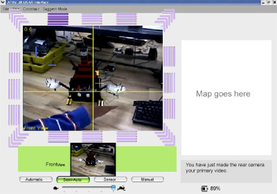
To keep the interface as simple as possible, we
decided to
include
he following: Front camera video,
rear
camera video,
camera position ( cross
hair overlaying the video), speed controls, battery, brake (when
on),
and
sonars.
Corner cases, such as low battery
wa
rnings
and
other
such
errors,
appear
when appropriate in the status bar (with the battery, speed control, and
brake).
The lowermost options are the Autonomous
modes.
There
are four. Safe, Shared, Tele-Op, and Escape.
Stage Three: Mock-ups, Interface problem-solving, and more Research
The AAAI Conference in San Jose gave us a chance
to observe robots interfaces. The co
nference provided
several interesting
pieces of information for us as both researchers
and developers and inspired some ideas for us moving forward.
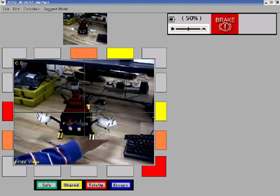
Stage Four: Designing
A preliminary design screenshot using Photosh
op appears below. We talked
about adjustments to the interface. At one point,
my mentality was
strongly
towards modeling the interface after a first person
shooter video game.
Stage Five: Gathering and processing data
Using screenshots of all of the competitors in ICJCA/AAAI 2003,
I measured the height and width of the video and maps. I also measured
the heights and
widths of the entire interface. I then multiplied
those heights and widths to arrive at an area in square pixels. I calculated
percentages by dividing the area of the total interface by the area of
the video and map.
The UMass Lowell video r
epresents 27% of the interface while the
video represents 19% for a total of 46%.
INEEL's video is 10% of the total interface while their map is
8%. The total area of the video and map is 18% of the screen.
| Percentage of IJCAI/AAAI 2003 USAR Interfaces dedicated to Video
and Map
components# |
| |
Video |
Map |
|
MITRE* |
9% |
57% |
| Rochester |
25% |
45% |
| New Orleans |
9% |
21% |
| Swarthmore |
15% |
14% |
| INEEL |
10% |
8% |
| UMass Lowell* | <
td>27%
19% |
#
*
We significantly increased the size of the
video and map from our original straw man interface. Because users give
their a
ttention to the video at the exclusion of other displays it stands
to reason
the video should be larger.
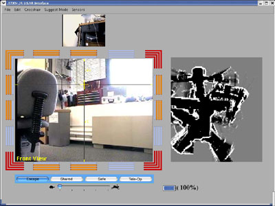
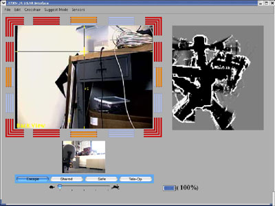
Stage Six: Final iterations, presenting, and wrap up
The map works, the interface compiles. We made a
the following
significant changes to the interface based on user testing.
Relative Controls: When the robot's primary view is the rear camera
it is the largest component of
the interface. After testing our first
design, we chose to make our controls and sonars relative to the rear. The right, left, forward, and back commands correspond to the primary video.
For example when the driver has the rear camera as the primary vi
deo, forward
moves the robot backwards.
Gradient Battery: When full, the battery
appears with five blue bars. As the power decreases
the colors change as well as the amount of bars in
the battery graphic.
When the battery is
near empty the battery graphic blinks. If there
is not enough power to go back to the robot's starting
location, a large empty battery graphic appears in
the video screen in red (see the brake error message in the Redundant
and Responsive Error Messages section).


Gradient Modes: Autonomy
modes appear from most autonomous to least. The user
has a better sense of continuity by both the location
and the mode colors.
Front a
nd Rear Camera Toggling: A "camera
view" button controls the robot's primary view.
The default view shows the front camera video as a
large video feed while the rear camera video appears
as a smaller video feed. For this elem
ent we drew upon
the analogy of a rear view mirror in a car. When the
user opts to change the camera view,
the rear camera appears significantly larger,
while the front camera recedes to the smaller
size.
Gradient Sonar: The sonars display bars to reinforce color
as
a feedback channel. The following five images represent the five states
of the sonar bars. When the sonars detect
no object, the four bars appear blue.
When an object is detected in the distance, the bar furthest from the video
appears green. As the
distance of an object decreases, more bars
appear shaded. When
an object is extremely close, all bars appear red.
Redundant and Responsive Error Messages: Research in human-robot
interac
tion tells us that users tend to pay so much attention
to the video, they fail to notice other interface components.
We decided to provide redundant error messages using graphical
overlay on the primary video screen.
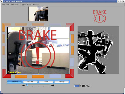
One such example is the brake. When the
brake is
on a small graphic appears in the upper right hand corner of the interface as shown below.
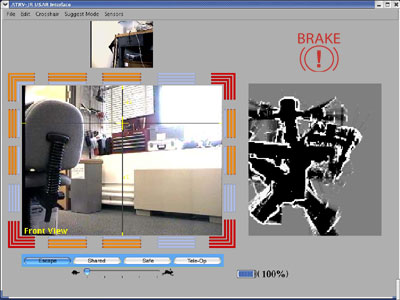
If, while the brake is engaged, the user select
s a direction
(forward,
backwards, left, right) in an attempt to move the robot this
indicates the user is unaware of the brake. A reinforcing
image
appears
on the video in the
form of a large brake graphic as shown below.
Grouped User Controls: User controls appear in one area below
the video feed.
Direct controls using a joystick and keyboard allow the user to select
modes and robot speed
without using a mouse, the
interface now displays both in the same area. By grouping
related functions (robot's autonomy and speed state), we reduce
cognitive load.
Human-Robot
Interaction: A Straw Man appr
oach to Interface Iteration -
Note on the presentation: Since much of the
lab
was
familiar
with Human - Robot
Interaction and USAR, the presentation is most
ly concerned with
the Human-Computer Interaction aspect of this project.
What we learned
One aspect of Human-Computer Interaction we attempted
to use throug
hout our design was color. In our design, color is
used to reinforce, rather than define interface
components. This is a very important principle for
color-blind users. The sonars provide an example.


The above blocks appear
ed in one of our early iterations.
The three boxes rely on color to communicate system
status to the user. If the user cannot distinguish
between the colors, he or she will not be able
to gain information from these interface components.<
br>


The above bars appear in our final iteration. While
the same colors appear, an
additional special cue communicates the system
status. Four bars appear. When a bar is off, it appears
as a color very similar to the inter
face background.
This color gradation theme also appears in our battery
and autonomous modes.
Early on in our work, we agreed the video should
be as large as possible. We discussed the advantages and disadvantages
of a full screen video feed with interface components appearing as graphical
overlay. Gamers who are familiar with first person shooters, can attest that
this style of interface is
not only usable, but fluid and intuitive.
In the end, we chose simply to increase the size of the video.
The limitations of the wireless network would have made the frame rate
of a full screen video unacceptable. We made the video portion of
the interface
as large as possible without sacrificing performance.
However, a large video feed is as an eventual direction as equipment and
wireless capabilities allow.
|